
HydroTreater Reactor Internals (under)performance
Operation environment
In today’s 10 ppm Ultra-Low Sulphur Diesel (ULSD) world, the HydroTreater (HT) or HydroDeSulphurisation (HDS) unit has become a high-margin upgrader which cannot perform without proper reactor internals. The catalytic reactions in the reactor are the heart of the HDS. To extract maximum value out of your catalyst batch requires uniform trickle flow conditions as well as control of the optimum temperature profile during its life cycle and the reactor internals need to safeguard this. Consequently, your reactor internals need:Unit health check
Unless a problem has clearly manifested itself – such as a pressure drop issue – it is wise to carry out a performance or health check every 1-2 years.
Such a health check evaluates the unit at various levels:
1.uniformly distribute feed + hydrogen
2.remove radials temperature differences,
3.mix cold quench fluids at the entrance of downstream beds and – last but not least &ndash
4keep the catalyst in place without leakage or blockage, Compact design and safe & easy maintenance are also important features of a good design. A regular check on above aspects assures the operator that their equipment is up-to-standard for a good catalyst performance. Solving maldistribution or fouling problems during the run is costly and needs effective troubleshooting to recover lost margin as quickly as possible.
Liquid distributors
In ULSD operation the preferred flow regime inside the catalyst bed is trickle or film flow. To fully use each catalyst pellet the bed has to be properly wetted during start-up. In this way unwanted rivulet flow (with the catalyst bed partially wetted) can be avoided. Next, a distributor needs to ensure that the untreated feed is homogeneously distributed over the reactor cross-section. This is usually done with an array of holes, downcomers or nozzles. Inside the catalyst bed liquid hardly “spreads out” any further, therefore the initial distribution needs to be as ideal as possible to avoid dry spots or maldistribution downstream. For example, tray levelness is very important to ensure all feedstock has the same reaction time in the bed: bypassed liquid will see less catalyst, resulting in too low conversion and thus will be off-spec! Depending on the type of tray, a few mm’s of tilt can already produce a significant maldistribution (see picture at the top).Quench systems
Removing temperature differences and mixing cold gas or liquid into the feed is usually carried out inside a quench box, located in between catalyst beds. Its 2-phase flows or “hydraulics” can be quite complex, also because little space is available to do the quenching and mixing. “On-the-run” quench tests can show if these systems work satisfactorily. Secondly, the regular turn-around inspection and cleaning is essential for correct operation. Because here “the devil is in the details” an inspection can easily miss essential aspects, so it needs to be based on solid understanding of how the internal works or should work. Finally, thermocouple indicator networks or grids in each bed are must-haves to control and monitor the catalyst activity in the reactor from feed entry to product exit. These grids should be designed and installed in such a way, that dense-bed loading as well as people entry is not hampered.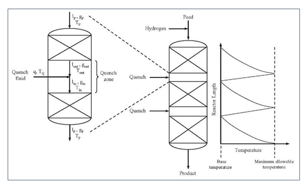
Anti-fouling trays
Usually, top bed grading is applied to absorb foulants in the feed before it can reach and block the conversion catalyst. However, in addition or alternatively, anti-fouling trays can also absorb or store significant amount of fines or corrosion products before it enters the top bed. These trays are usually placed in the free space of the upper dome of the vessel. At a catalyst change-out, these trays have to be cleaned for re-use.Catalyst removal: dumping vs vacuuming
Every catalyst change-out starts with removing the old batch. This can be done by dumping over the bottom or vacuuming over the top. The former is the least costly as well as the fastest method. The latter takes more time and can result in high cat losses to breakage and attrition: if the batch is regenerable, the costs are an additional catalyst top-up. Modern reactors have special nozzles at the bottom side of each bed for easy dumping of the catalyst. Older vessels normally do not have such separate “side dump nozzles” but all catalyst has to move to the bottom bed through so-called “internal dump pipes” before it can be discharged from the bottom of the vessel. However, these open dump pipes are possible bypasses for the liquid feed and can be prone to catalyst leaks. Therefore, proper design and regular inspection have to ensure that your dump pipes will function when they are needed, but without any nuisance effects during the cycle itself.Summarising
A reactor internals check allows you to extract maximum benefit from your catalyst.Check also our page Optimal Catalyst Performance
Catalyst-Intelligence is a consulting company providing independent & comprehensive advice on fixed bed catalysts to refineries and petrochemical plants.
For more information on how we can help you we refer to our website: www.catalyst-intelligence.com